[ad_1]
On this USB-C collection, we’ve coated fairly a little bit of USB-C – issues which are well-known, issues that needs to be higher identified, and a pair issues that simply appeared on-line for the primary time. We’ve coated virtually all the pieces in some depth besides USB Energy Supply. I’ve described the method a bit within the “Energy” article, however that was principally about find out how to use PD by merely shopping for the suitable resolution. Nevertheless, that’s not sufficient for a hacker. Let’s see if we will make our personal PD set off board.
PD Set off Board In 100 Traces Of Python
We’ll begin with no pre-existing software program stack – we’ll take a PD PHY (bodily layer interface) chip, join it over I2C, toggle its registers ourselves, and do our personal packet crafting. I’ll use MicroPython, as a result of I discover it really works finest for instructional functions; plus, I genuinely like writing Python for {hardware} tinkering functions, and I hope you may admire the advantages as effectively.
Our goal for at this time? Getting 9 V voltage out of a USB-C PSU, brief and candy; principally, what each single set off board out there may be constructed to do. After we attain this goal, you’ll have the ability to create your personal set off boards – however method cooler, customizable, with value seemingly similar to a set off board chip; plus, in Python, no much less! Oh, and it’ll take us below 100 strains of Python code to get there.
Minimal {Hardware} Necessities
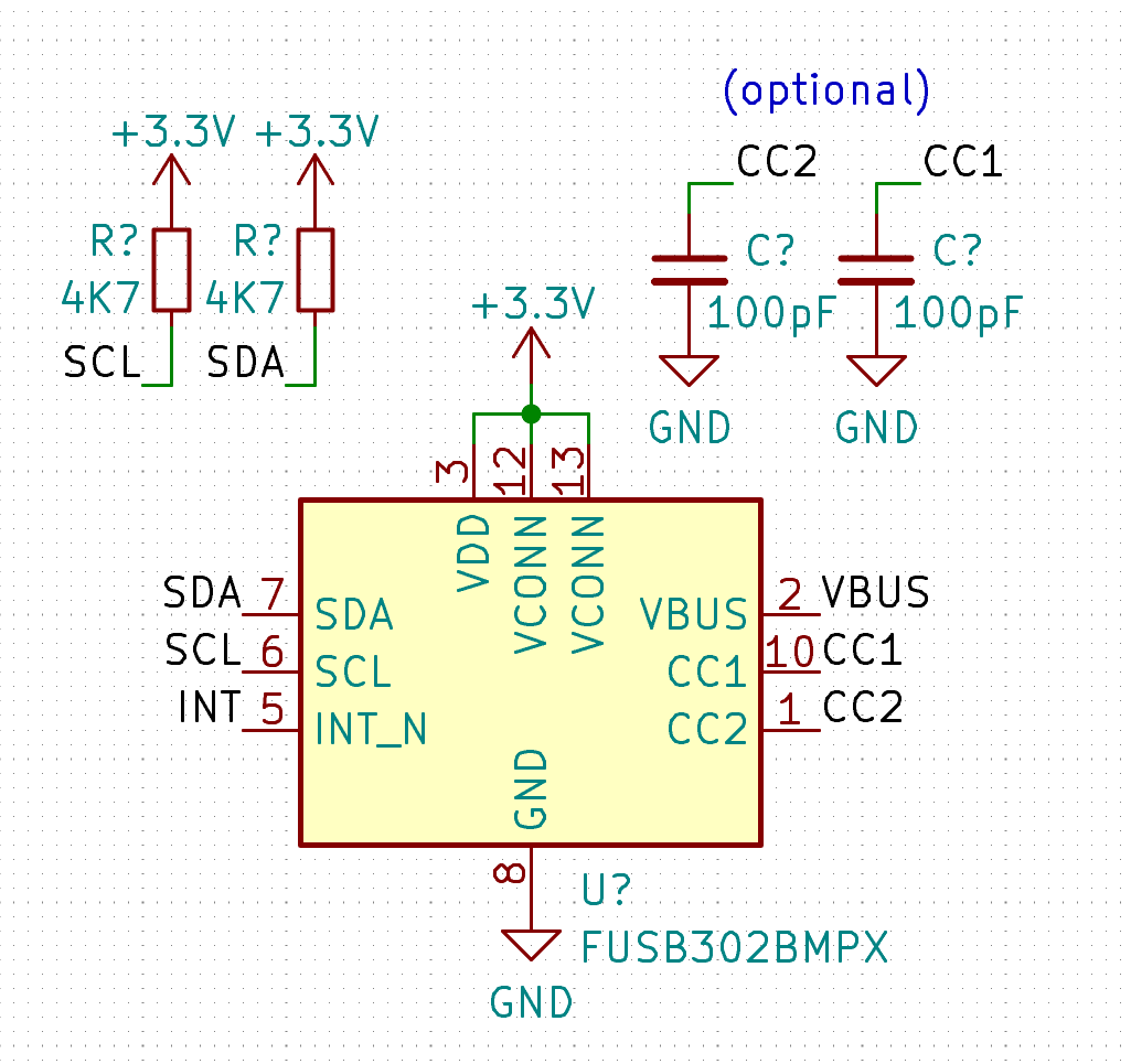
If you wish to observe alongside, you’ll need the FUSB302 chip, and a few type of MicroPython board. I’m utilizing a RP2040+FUSB302B mixture on a devboard of my very own design, however an ESP8266 would just do as effectively. FUSB302B is the brand new and seemingly functionally an identical possibility – undecided what the variations are, and I’m fairly certain they received’t matter to us.

Niceties? It’d be good in case you may connect an LED to VBUS; having a 1 kΩ resistor in collection must be sufficient for even 20 V on VBUS. I think about some LEDs may get sad at 17 mA, however most ought to survive simply high-quality; in the event that they don’t, exchange the LED and double the resistor. This shall be helpful throughout debugging afterward! You don’t have to attach the USB-C port’s VBUS to the FUSB’s VBUS, although, it would assist afterward if constructing a extra correct system is your intention. Completely do make VBUS accessible to be able to probe it with a multimeter and examine whether or not your code has run efficiently!
Software program Setup
For a begin, obtain the FUSB302 datasheet, in addition to the USB PD specification, model 3.0 – we are going to confer with them each. Having each of them open whereas taking part in with PD is extremely suggested, in truth! That mentioned, for this installment, we are going to solely want the FUSB302 datasheet.

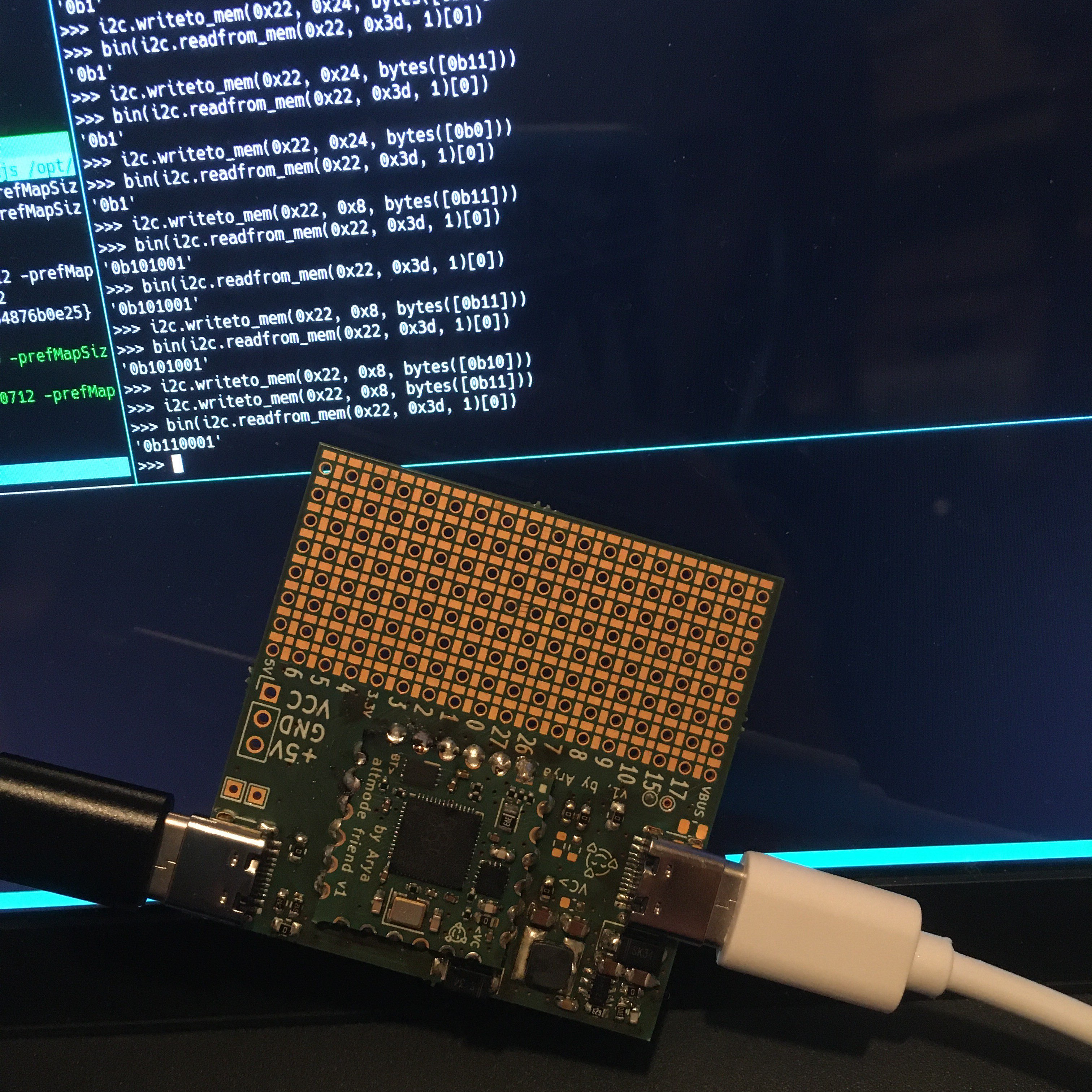
0x22 seem once you do i2c.scan()? Then you definitely’ve wired all the pieces up accurately! Does it not seem, or does the initialization fail? Ensure that your pins are outlined correctly, and you’ve got pullups on I2C pins.
When an I2C system seems, you may mess around. Attempt to learn the 0x01 model and revision register. Generally, seek the advice of the FUSB302 register map – it begins at datasheet web page 18, and also you’ll be leaping round these pages for a bit as you play! Reminder on find out how to learn and write registers of an I2C system in MicroPython:
# Writing 0xAA and 0x55 to deal with 0x22, register 0x3e
i2c.writeto_mem(0x22, 0x3e, bytes([0xAA, 0x55]))
# Studying one byte from tackle 0x22, register 0x43
knowledge = i2c.readfrom_mem(0x22, 0x43, l)
# kind of 'knowledge' shall be 'bytes', convert as wanted, or simply print it
Able to proceed? Let’s swap away from REPL at this level – as an alternative, I counsel you place code right into a essential.py doc, switch it to the board, then run it each time you want to take a look at it. My workflow for this mode is working a tmux session cut up into separate tabs for a terminal-based code editor and for a serial terminal/code add shell – for code add, I take advantage of ampy. If you happen to’re in search of one thing GUI-based, I’ve had buddies efficiently use uPyCraft.
If you happen to’re following this tutorial from CircuitPython, first, that’s admirable and I hope it’s simple sufficient so that you can adapt the examples, and second, you will have a bonus – it will likely be simpler so that you can add your code, since CircuitPython helps storage system mode on issues just like the RP2040. Nevertheless, there’s a drawback too – you’ll must put extra effort into debugging, since CircuitPython doesn’t allow you to introspect your code in REPL after it crashes – a minimum of, it didn’t let me do it final time I attempted, and that appeared to be a basic limitation.
Setting The Chip Up
First, we have to set a number of registers within the FUSB302. These settings assume {that a} USB-C cable is plugged in; a minimum of, most of them function below such an assumption. I may set you up with a extra refined setup, however that’s not what this text is for – at this time, we’re getting the next voltage out of a PSU we have now related, and we don’t want a lot for that.
First, a very good apply is to reset the FUSB302 – who is aware of in case your MCU has simply been rebooted. Write 0x01 to 0x0c (RESET) register for that. 0x02 will reset the PD logic – we’ll want that later. Then, we have to get the chip’s totally different components out of sleep – writing 0x0f to 0x0b (POWER) register will do. Write 0x00 to 0x06 (CONTROL0) to unmask all interrupts, then 0x07 to CONTROL3 to allow packet retries. Now, we’re prepared to find out the CC polarity!
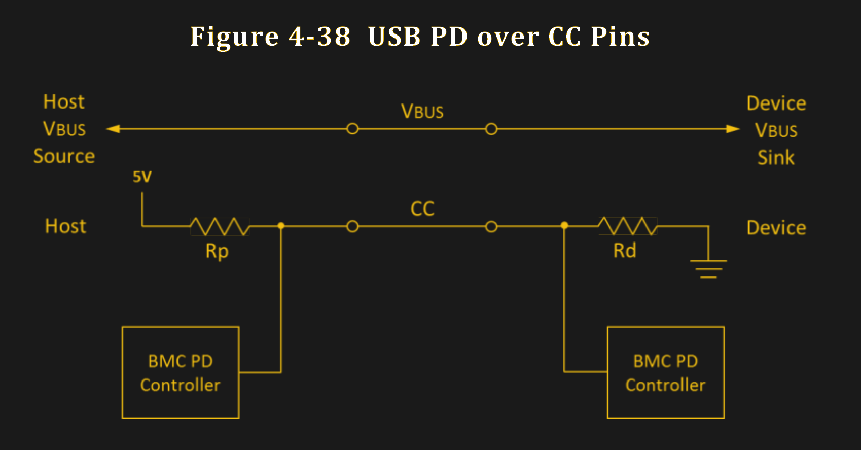
The FUSB302 has pulldown resistors applied by default, and whereas we may detach them, they do assist, as we’re working with a PSU proper now – which has a pullup on the CC line. The PD communication solely occurs on one of many CC pins, and by measuring which one in every of them has a supply pullup connected, we will decide which pin is related to the PSU. The particular method to do that, I’ve borrowed from the Pinecil’s FUSB302 initialization code, by way of snooping upon it a logic analyzer. Nevertheless, I’ve seen this precise technique performed in different FUSB302-aimed libraries as effectively.
This might very effectively be a cargo cult measure, on condition that one may theoretically use the port position computerized toggle (see CONTROL2) characteristic of the FUSB302 – I didn’t get that one to work effectively for me, nonetheless. Till now – the Pinecil implementation that I discovered from, occurs to be sink-only, and makes use of a guide measurement technique. It’s simple – connect with CC1, measure the voltage, connect with CC2, measure the voltage, then examine. The FUSB302 has two handy bits that convert CC pullup voltage to USB present ranges allowed, and we will simply examine these two bits between two reads.
First, write 0x07 (0b111) to 0x02 (SWITCH0), connecting the inner ADC to CC1 – then, learn 0x40 (STATUS0), and get the bits 1-0 from that; these bits signify present ranges, and the non-connected pin will point out zero. Then, swap the ADC to CC2 by writing 0x0b (0b1011) to SWITCH0, and skim STATUS0 once more. If the CC1 worth is bigger than CC2, then the PSU is related to CC1, and vice-versa. If each the CC1 and CC2 studying are at zero, then there’s no PSU detected – that’s the place you add a “nothing detected” particular case to your code, after which maybe look forward to a PSU to be connected. Alternatively, as a homework task, you may try to get the toggle characteristic working!
Beginning The Transmitter Has Penalties
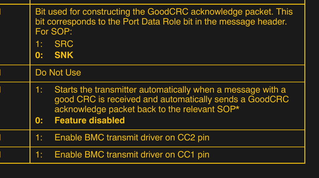
We now know the CC pin to function on – let’s make use of that. Say, our pin is CC1. We allow each the obtain and transmitter on it, in addition to computerized GoodCRC responses. Write 0x25 (0b100101) to 0x03 (SWITCH1) register – bits 0-1 will change relying on which CC pin you need the transmitter to hook up with, bit 2 permits computerized GoodCRC responses, and bits 5-6 say that we’re going to speak PD revision 2.0. We’re truly going to be speaking PD 3.0, however the FUSB302 datasheet hasn’t been up to date to say that it’s outright supported, regardless that it appears to be absolutely functionally appropriate so far as I’ve been advised. Then, write 0x07 to the SWITCH0 register – connecting the measure block to the CC1 pin, similar to after we have been measuring it.
The GoodCRC half is a “level of no return” of kinds. The GoodCRC message transmission implies that, whether or not you’re speaking to a PSU or a tool, the opposite aspect primarily receives ‘message acknowledged’ responses to no matter they despatched. Briefly, sending GoodCRC responses is an indication of clever life despatched to the system on the opposite aspect of the USB-C cable. Some USB-C messages, nonetheless, additionally require an clever response inside a sure timeframe after they’ve been obtained – in case you ship a GoodCRC response robotically, however then don’t ship a response anticipated, that may incur a ‘one thing went unsuitable’ response on the opposite finish.

Nonetheless, we must always do a little bit of cleanup earlier than we begin receiving messages. Write 0x40 into 0x06 (CTRL0) to flush the TX buffer, 0x04 into 0x07 to flush the RX buffer, and 0x02 into 0x0c (RESET) to reset the FUSB’s inner PD logic.
Now we’re all set – the messages shall be coming into the FUSB302’s obtain buffer, and we’ll have the ability to learn them.
Getting Messages
A PD PSU will robotically ship out a message with its capabilities, and it’ll attempt to try this a number of occasions after power-up – till the second {that a} message is acknowledged with our GoodCRC. As your board is presumably not powered from the identical USB-C port, it is possible for you to to obtain the message from contained in the REPL and poke at it – nonetheless, do do not forget that the PSU will timeout except you’re in a position to request a profile on time, and also you received’t have the ability to do this interactively; in different phrases, you want to craft a response robotically. Nonetheless, we can just do that pretty simply!
How do you examine whether or not there’s one thing within the obtain buffer? Learn the 0x41 (STATUS1) register and examine the bits 5-4: bit 5 shall be set to zero when the obtain buffer incorporates one thing. Then, you may learn bytes out of the buffer – with a block learn, from the 0x43 tackle. The buffer may comprise a number of messages without delay, nonetheless, in a easy USB-C PD energy provide state of affairs, you may count on there to be one message.
You don’t must rigorously learn a single message’s value of bytes for now – for ‘checking that issues work’ functions, you may simply learn your entire buffer, which is 80 bytes lengthy. Let’s just do that!
>>> b = i2c.readfrom_mem(0x22, 0x43, 80)
>>> b
b'xe0xa1a,x91x01x08,xd1x02x00x13xc1x03x00xdcxb0x04x00xa5@x06x00<!xdcxc0Hxc6xe7xc6x00x00x00x00x00x00x00x00x00x00x00x00x00x00x00x00x00x00x00x00x00x00x00x00x00x00x00x00x00x00x00x00x00x00x00x00x00x00x00x00x00x00x00x00x00x00x00x00x00'
We Acquired Contact!
We obtained our first message! And we solely wanted to observe a comparatively easy initialization sequence – this isn’t all that a lot tougher than taking part in with a HD44780 LCD; and you could possibly certainly stuff this code into an ATTiny, even. I’d wish to thank [Ralim] and [Clara Hobbs] for laying the groundwork; the instructions I’m describing, are theirs to have found out – I couldn’t work out the complete sequence on my own, so, a number of the “which instructions are literally wanted for it to work” was taken from their stacks.
Within the subsequent article, we are going to parse this message and craft a correct reply to it! I’ve to apologize for leaving you on a cliffhanger, however correctly strolling you thru parsing messages will take a little bit of time. Nevertheless, you don’t must do any FUSB302 configuration anymore – you’re already ready to answer with a PD message, as quickly as you may craft an appropriate reply. Do you’re feeling impatient? Need to do it your self, as homework? Right here’s my code for parsing such messages, right here’s IronOS code accountable for a similar, and right here’s my pretty-printed I2C communications seize of a Pinecil negotiating the next voltage profile. In any other case, we’ll end this subsequent week!
[ad_2]
